

- Ամփոփում
- Առաջարկվող արտադրանքներ
I. Նկարագրություն
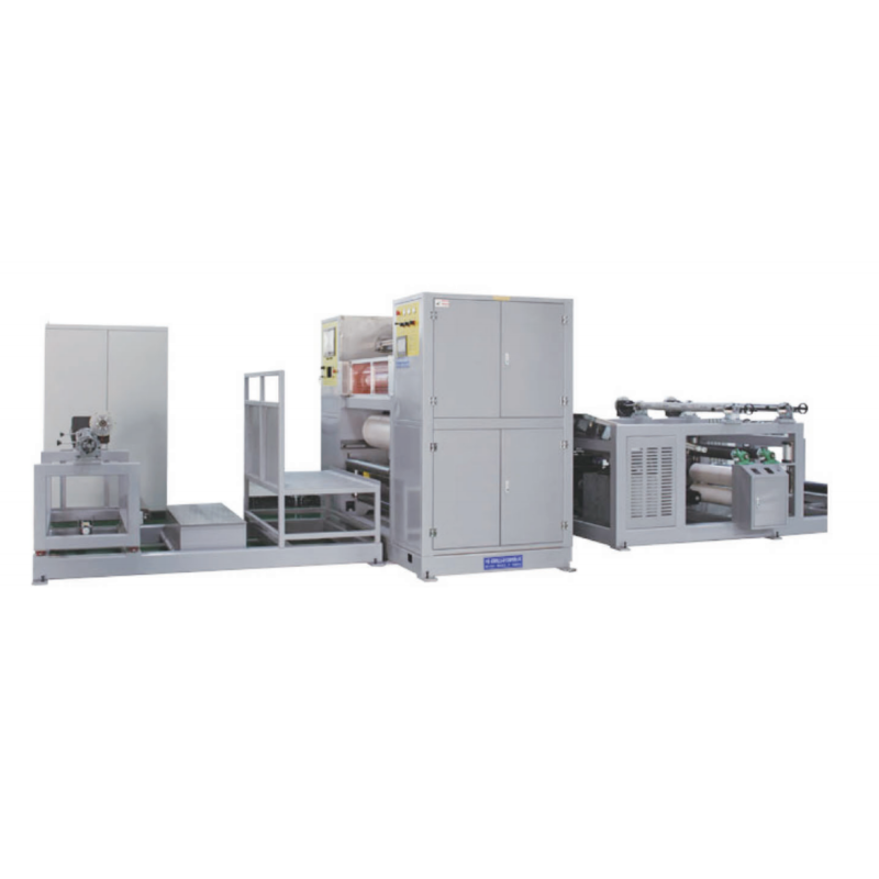
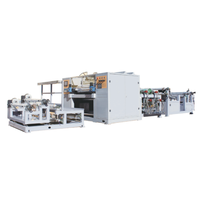
Այս արտադրական գիծը լիովին օգտագործում է նմանատիպ սարքավորումների ներքին և արտասահմանյան առավելությունները և մշակված ու արտադրված է բարձր մակարդակի պրեպրեգի արտադրական գիծ, որը ստեղծվել է անընդհատ բարելավումների և իրական արտադրական ու արտադրամասային գործընթացներում կատարված բարելավումների միջոցով: Հիմնականում օգտագործվում է ճապոնական տեխնոլոգիան՝ ածխածնի մետաղալարի պրեպրեգի համար (արտադրական գծի ընդհանուր երկարությունը 24 մետր է)
프로그ր램ի 특징:
1. Թելերի տարածման եղանակ՝ 4 շարժում ձախ-աջ, 1 թրթռում վերև-ներքև:
2. Հաստատուն լարման անվել, անվելի մասը սարքավորված է լարման սենսորով, որը կարող է կառավարել անվելը հաստատուն լարման պայմաններում:
3. Մատակարարումը ինքնակարգավորվում է, իսկ մատակարարման մասը սարքավորված է ինքնակարգավորման սարքով:
4. Դիպչելու էկրանով CNC կառավարման ինտերֆեյս՝ առանձին կառավարման վահանակով, 10 դյույմանոց դիպչելու էկրան + PLC օպերացիոն համակարգ, հեշտ է օգտագործել և կայուն է աշխատանքում:
5. Ավտոմատացված ջերմաստիճանի կառավարման համակարգը զինված է ջերմաստիճանի գրանցիչով, որը կարող է իրական ժամանակում հսկել արտադրական գծի ջերմաստիճանի փոփոխությունները:
6. Ռոլիկը զինված է բացվածքի կարգավորիչով, որը հնարավորություն է տալիս ճշգրիտ կարգավորել ռոլիկների միջև եղած բացվածքը, ինչը հանգեցնում է ածխածնի ստվարաթղթի որակի ճշգրիտ կառավարման:
II. Կարգավորվող հումքի պարամետրեր
Մանրաթելային նյութ՝ ապակե մանրաթել և ածխածնի մանրաթել
Ազատման թուղթ՝ CCK/PEK
(1) Հաստություն՝ 100–150 մկմ, առավելագույն լայնություն՝ 1270 մմ:
(2) Առավելագույն անբացվող տրամագիծը՝ φ800, առավելագույն բեռնվածությունը՝ 1000 կգ:
(3) Երկկողմանի սիլիկոնային թաղանթապատ թուղթ է, որը սոսնձման հետևանքով պետք է պաշտպանված լինի խոնավությունից:
Պաշտպանիչ թաղանթ՝ PE թաղանթ, հաստություն՝ 20–50 մկմ
Ռեզին՝ Էպոքսիդային ռեզին՝ 8000–200000 սանտիպուազ
Վերագլանցման և անվելու թղթե խողովակի ներքին տրամագիծը՝ φ76, թաղանթապատման թղթի առավելագույն անվելու տրամագիծը՝ 800 մմ
2. Սարքավորման պարամետրեր
(1) Ռոլիկի մակերևույթի լայնություն՝ 1400 մմ, ռոլիկի տրամագիծ՝ φ400 մմ
(2) Մանրաթելի գործվածքի լայնություն՝ 500–1000 մմ
(3) Ածխածնային մանրաթելի գործվածքի արտադրության արագություն՝ 2–15 մ/րոպե, կարելի է ճշգրտել շոշափման էկրանի վահանակի միջոցով
(4) Տաք յուղի ջերմաստիճան՝ առավելագույնը 120 °C, ջերմաստիճանի հավասարակշռություն՝ ±0,5 °C
(5) Սառը ջրի ջերմաստիճան՝ առավելագույնը 8 °C
3. Վերջնական արտադրանքի սպեցիֆիկացիա
(l) Արտադրանքի սպեցիֆիկացիա՝ 100 գ–800 գ ածխածնային մանրաթելի գործվածք կամ համապատասխան ապակե մանրաթելի գործվածք
(2) Արտադրանքի լայնությունը՝ առավելագույնը 1270 մմ
(3) Ռեզինի պարունակությունը՝ 24–60 % ± 3 % (զանգվածի շեղումը՝ ≤ ±3 %)
3. Լրացուցիչ սարքավորումներ (մատակարարվում են գնորդի կողմից)
(1) Էլեկտրական մատակարարում՝ 380 Վ × 50 Հց × 3 փուլ
(2) Մեկ 2,2 կՎտ օդային սեղմիչ, օդի մատակարարման ճնշում՝ 0,6 ՄՊա, մեկ 0,8 մ³ տարողությամբ օդի պահեստավորման տանկ
(3) Կրանի հուկը պետք է գետնից ոչ պակաս 3,5 մետր բարձրության վրա լինի
II. Սարքավորման կազմ
Սարքավորումը բաժանված է թելերի ստանդակի, ստորին թղթի և ֆիլմի վերապտույտման սարքի, վերին թղթի և ֆիլմի վերապտույտման սարքի, համատեղված թելերի տարածման մասի, նախնական արտադրանքի սեղմման մասի, տաքացման, սառեցման և վերին
թղթի ու ֆիլմի վերապտույտման մասի:
1. Թելերի ստանդակ՝ ներառյալ թելերի ստանդակը, միջին սանրի շրջանակը և թելերի հենարանը
Ածխածնի թելերի կամ ապակե մանրաթելերի կոները տեղադրվում են նախնական իմպրեգնացիայի և լամինացիայից առաջ կրիլի վրա: Թելերի կոները սիմետրիկորեն են տեղադրվում կրիլի ձախ և աջ կողմերում: Դրանք բաժանված են վեց շերտի՝ վերևից ներքև: Առջևի և հետևի մասերում ընդհանուր առմամբ կա 15 թելերի կոների սյուն: Միաժամանակ կարող է նախնական տեղադրվել ընդհանուր առմամբ 180 թելերի կոն: Թելերը անվելով արտադրում են ածխածնի կամ ապակե մանրաթելերի սովորական գործվածք: Յուրաքանչյուր շերտի վրա տեղադրված է թելերի հենարանի ձող, որը պատրաստված է φ12 փայլուն առանցքից: Թելերի փաթեթները անցնում են թելերի հենարանի ձողի միջով, որպեսզի թելերի փաթեթները չխաչվեն միմյանց հետ և խուսափեն թելերի փաթեթների միմյանց մեջ մտնելու, միմյանց ձգելու, պտտվելու և պտտվելու հնարավորությունից:
Կրեյլը 4 մետր երկարություն ունի, 2,15 մետր բարձրություն և 1,12 մետր լայնություն: Առջևի ծայրը սարքավորված է թելերի բաժանման ատամներով և յուրաքանչյուր շերտի թելերի կոների համար նախատեսված կրեյլի ուղեցույց ռոլիկներով: Թելերի բաժանման ատամները և ուղեցույց ռոլիկները թույլ են տալիս յուրաքանչյուր թելի փունջին մտնել միավորված թելերի տարածման մեխանիզմ՝ հնարավորինս փոքր միմյանց մեջ մտնելով:
Թելերի տարածման մեխանիզմի մեջ մտնելուց առաջ թելի փունջը անցնում է միջին սաղավարտի շրջանակի և թելերի աջակցող շրջանակի միջով՝ հետագայում կարգավորելու թելերի շարժման դիրքը և կենտրոնացնելու թելի փունջը ուղղահայաց ուղղությամբ:
2- Ստորին թղթե ֆիլմի վերապտույտման միավոր
Ռեզինով պատված թղթե փաթեթը տեղադրվում է ստորին թուղթ և ֆիլմ վերապտույտող սարքի վրա՝ օգտագործելով օդային ընդլայնվող առանցք: Այն բաժանված է հիմնական մասի, ճանապարհի, ճշգրտման և փաթեթավորման սարքի, արգելափակման մեխանիզմի և այլն:
Շարժական հետագիծը թույլ է տալիս մեքենայի մարմինը ճշգրիտ դիրքավորել նույն դիրքում յուրաքանչյուր բեռնավորման և անբեռնավորման հետևանքով: Այն հիմնականում կազմված է 60x40x4 անկյունաձողից և 60x10 հարթ ստալից կառուցված շրջանակից, որի մեկ ծայրը բաց է: Բաց ծայրում տեղադրված է սահմանափակման սարք, իսկ թղթե վագոնի առջևի անիվը դուրս է գալիս հետագծից: Կան չորս սահմանափակման կապարանների հենարաններ:
Մարմնի ստորին կողմի չորս անկյուններում տեղադրված են շրջանակավոր անիվներ՝ մարմնի համար հենարան ապահովելու նպատակով: Շրջանակավոր անիվները ներառում են անիվներ և սահմանափակման ռոլիկներ: Դրանց հիմնական ֆունկցիան մեքենան աշխատանքային դիրքից դուրս քաշելն է, վերամշակվող ֆիլմի փաթեթի անբեռնավորումը, ռեզինապատ թղթի փաթեթի բեռնավորումը և այն վերադարձնելը աշխատանքային դիրքին: Մարմնի ստորին կողմի մեջտեղում տեղադրված է սահմանափակված անիվների շրջանակ, որտեղ նույնպես կան սահմանափակման ռոլիկներ: Շրջանակավոր անիվների և սահմանափակված անիվների շրջանակի ռոլիկները կանխում են թուղթ տեղադրող և ֆիլմ հավաքող վագոնի շեղումը աշխատանքային դիրքից:
Ճշտման և մատակարարման մեքենան տեղադրված է հիմնական մեքենայի մարմնի ձախ կողմում և միացված է հիմնական մեքենայի մարմնին սահքի ռելսային սահիկով, որը թույլ է տալիս սահել և հեշտացնում է ճշտման շարժումը. աջ կողմում մեքենայի մարմնին ամրացված է ֆիլմի մատակարարման բռնակ:
Հիմնական մեքենայի մարմնի կողմում ճշտման մեքենայի կողմին տեղադրված է արգելափակման մեխանիզմ. Երբ մեքենայի մարմինը հասնում է աշխատանքային դիրքին, արգելափակման մեխանիզմը ամրացնում է մեքենայի մարմինը ռելսին՝ կանխելու մեքենայի մարմնի դիրքից շեղվելը մեծ ձգողական ուժի ազդեցությամբ:
Մեքենայի մարմինը պարունակում է մատակարարման երկու ճյուղավորված առանցքի համալիր, մեկ շեղման ճշտման համակարգ, երկու օդային ընդլայնվող առանցքի նստատեղեր, երկու թղթի ուղեցույց գլաններ և ֆիլմի մատակարարման ճյուղավորված առանցքի համալիր, որը ներառում է սերվոմետր, արագավելիչ, ստայնակ և ճյուղավորված առանցք և այլն: Մատակարարման ճյուղավորված առանցքի համալիրը ներառում է բռնակը, ճյուղավորված առանցքը, մագնիսային փոշու արգելակը, փոխանցման ատամնավոր ամբողջականությունը և այլն:
Կապված հարթեցման և ծռման գլանները տեղադրված են թելերի տարածման շրջանակում:
Լարման սենսորավորված գլանների խումբը տեղադրված է թելերի տարածման շրջանակի ներսում, ներառյալ երկու բռնակ, 3 ուղեցնող գլան և 2 լարման սենսոր: Երկու օդային ընդլայնվող առանցքներ սարքավորված են օդային զենքերի և սպիրալաձև խողովակների մեկ համալիրով և նաև տեղադրված են թելերի տարածման շրջանակի առաջային մասում:
Դրագ-շղթաները տեղադրված են մեքենայի մարմնի կողմերին՝ մեքենայի մարմնի տարբեր միջոցառումների ստանդարտացման համար:
3- Վերին թղթե ֆիլմի վերապտույտման միավոր
Վերին թղթի դնելու և ֆիլմի հետաձգման մեխանիզմը տեղադրված է թելերի տարածման մեխանիզմի վերին կողմում գտնվող վերին թելերի տարածման սայլակի վրա: Ներառված սարքավորումները մոտավորապես համարժեք են ստորին թղթի դնելու և ֆիլմի մատակարարման սայլակի սարքավորումներին: Մեկ հատ անվերջացվող սայլակի միացման առանցքի հավաքածու, մեկ հատ ճշգրտման համակարգ, երեք հատ օդային ընդլայնվող առանցքների նստատեղեր, երկու հատ ֆիլմի մատակարարման սայլակի առանցքների հավաքածու, մեկ հատ ճշգրտման և անվերջացվող սայլակ, լարման զգայչի գլանների հավաքածու (ներառյալ երկու բռնակ, երեք ուղեցույց գլան, երկու լարման զգայչ): Երեք օդային ընդլայնվող առանցքների հետ մեկտեղ տրվում է օդային ատրճանակների և սպիրալային խողովակների մեկ հատ հավաքածու:
Մինչև վերին ազատման թուղթը մտնի պրեպրեգի սեղմման գլանների խմբի մեջ, ազատման թղթից հանվում է պաշտպանիչ ֆիլմը: Ֆիլմի մատակարարման երկու սայլակի առանցքների հավաքածուներ հավաքված են և հերթափոխային կերպով կատարում են ֆիլմի մատակարարման աշխատանքը:
4- Թելերի տարածման մասը
Միավորված թելերի տարածման մասը տեղադրված է թելերի տարածման շասսիի վրա և ներառում է թելերի բաժանիչ համալիրը, ձգող ռետինե վարորդավոր վարդակների համալիրը, ծաղկավոր վարդակի թելերի տարածման համալիրը, մեծ թելերի տարածման համալիրը և այլն:
-1. Թելերի բաժանիչ համալիր
Թելերի փունջը առաջին հերթին մտնում է թելերի բաժանիչի մեջ՝ անցնելով թելերի պահարանի միջով: Շրջանակը բաղկացած է 2 կողային սալիկներից, 1 ստայնդից և երկու ամրակներից: Թելերի բաժանիչի առաջային մասում տեղադրված է լրիվ տրամագծով առանցքի համակցումը և ուղղելու համակցումը: Այստեղ երկու համակցումների միջոցով ուղղվում են թելերի փնջի փոքր քանակությունը, որոնք պտտվում են: Հետևյալ մասում տեղադրված են թելերի բաժանման սալիկները, սկզբնական թելերի տարածման վարդակները և այլն: Ուղղելու համակցումը բաղկացած է 2 ուղղելու նստարաններից, մեկ նվազեցնող շարժիչից, մեկ փոխանցման առանցքից, մեկ զույգ փոխանցման ատամնավոր ամբողջականությունից, երկու զույգ սահքի ռելսերից, մեկ կամարից, մեկ ճանկավոր վարդակից, 2 սահքի մասերից և այլն:
-2. Ձգող ռետինե վարդակների համալիր
Օգտագործեք այն սկզբնական թելի մտցման և սխալների վերացման ժամանակ, իսկ այլ դեպքերում չօգտագործեք: Այն բաղկացած է ռետինե վահանակների զույգից, նվազեցնող շարժիչից, փոխանցման ատամնավոր անվայից և ատամնավոր անվայից, ճնշող գլանից, սահքի ռելսի սահարանից և համապատասխան ստայակից:
-3. Ծաղկավոր վահանակի թելի տարածման հավաքածու
Հենարանային համակարգը բաղկացած է երկու հենարանային պատերի զույգից և երկու հենարանից: Աշխատանքային մասերը ներառում են շարժվող ծաղկավոր վահանակ և երկու ձգող ծաղկավոր վահանակ: Շարժվող ծաղկավոր վահանակը շարժվում է սերվոշարժիչի կողմից, իսկ երկու ձգող ծաղկավոր վահանակները՝ համապատասխանաբար աջ անկյան նվազեցնող շարժիչների կողմից: Արագությունը կարող է կարգավորվել շարժիչի վահանակի միջոցով՝ ըստ ցանկության: Նմուշավորող վահանակի ստորին կողմում տեղադրված է տաքացման լամպի մետաղապատ սալիկ, իսկ թելի փունջը նախատաքացնելու համար տեղադրված են երեք 1,5 ԿՎտ ածխածնային մանրաթելի տաքացման լամպ:
-4. Dazhan թելի հավաքածու
Հենարանային համակարգը բաղկացած է երկու մեծ հենարանային պատերից և երեք հենարաններից: Աշխատանքային մասերը ներառում են երեք թելերի բաժանման ուղեցույց ռոլիկներ, երկու բարձրացման ուղեցույց ռոլիկներ, չորս տեղափոխման ռոլիկներ և երկու թելերի դողացման ռոլիկներ, որոնք տեղադրված են հերթափոխային կերպով: Դրանց հետևում տեղադրված են երկու անցումային ռոլիկներ, որոնք մաքրորեն դասավորված թելերը ուղարկում են առաջին պրե-պրեգ լամինացման ռոլիկների համակարգին:
Բարձրացման ռոլիկի երկու ծայրերն էլ ամրացված են համապատասխանաբար երկու ուղղահայաց տեղադրված սինխրոն բարձրացուցիչների ստեղների ծայրերում գտնվող մոնտաժային նստատեղերին: Երկու բարձրացուցիչների միջև միացված է սինխրոնացման առանցք՝ բարձրացման սինխրոնացումը պահպանելու համար: Օգտագործման ժամանակ այն բարձրանում է, իսկ չօգտագործելիս՝ իջնում:
Յուրաքանչյուր շարժվող ռոլիկ շարժվում է սերվոշարժիչի կողմից և կառավարվում է առանձին՝ հերթափոխային կոորդինացիայի միջոցով թելերի փաթեթները տարածելու և դասավորելու համար: Մյուս հավելյալ մասերը ներառում են շարժիչի սահմանափակիչ հենարան, էկսցենտրիկ տեղափոխման H անիվ, սայլակներ և գրաֆիտային պղնձե մասեր և այլն:
Թելի ցնցման ռոլիկների համակարգ՝ բաղկացած է սերվոշարժիչից, միացման սարքից, շարժիչի ստայակից, թրթռման կամերայից, կամերայի առանցքից, սահքի ռելսերի զույգից, սեղմման զսպանակից, արգելակման և միացման մեխանիզմի համադրությունից, սայլակներից և այլ մասերից:
Երկու անցումային ռոլիկների համադրություն՝ սա թելի բացվելուց հետո և պրեպրեգի սեղմման առաջ վերջնական ճշգրտման ռոլիկների համադրությունն է: Այն բաղկացած է ամրացված ստայակից, անցումային ռոլիկից, սայլակից, միացման օղակից, առանձին առանցքի ամրացման օղակից և համապատասխան այլ աքսեսուարներից: Առաջին անցումային ռոլիկի երկու ծայրերը սահմանափակված են առանձին առանցքի ամրացման օղակներով՝ ցանցի եզրային դիրքերը երկու կողմերում ստանդարտացնելու համար: Միացման օղակը թույլ է տալիս առաջին անցումային ռոլիկին ընտրել՝ պտտվի թե ոչ:
Դազհան թելի մեջքի վրա տեղադրված է թղթի ուղեցույց ռոլիկ՝ պաշտպանական թաղանթի վերամշակման աջակցության համար:
5- Պրեպրեգի սեղմման մաս՝ օգտագործվում է թելի և սմուրի միջոցով գործվածքի ձևավորման համար:
Սինթետիկ մատերիալների նախնական պրեգրեսավորման գործընթացը հիմնականում իրականացվում է վեց շարք տաքացվող ռոլիկների միջոցով: Չորս ռոլիկների խմբերի կառուցվածքները հիմնականում նույնն են: Առաջին ռոլիկների խմբի առաջ ավելացված են միայն երկու սառեցնող ռոլիկ՝ մեկը վերևում և մեկը ներքևում: Երբ վերին ազատման թուղթը անցնում է վերին սառեցնող ռոլիկի միջով, PE ֆիլմը անջատվում է ազատման թղթից և վերին ֆիլմի մատակարարման եռաձև առանցքի միջոցով հավաքվում ու վերամշակվում: Երբ ստորին ազատման թուղթը անցնում է ստորին սառեցնող ռոլիկի միջով, PE ֆիլմը նույնպես անջատվում է ազատման թղթից և թղթի անվելու մեքենայի ֆիլմի մատակարարման եռաձև առանցքի միջոցով հավաքվում ու վերամշակվում:
Վերին ազատման թղթի սոսնձվող մակերեսը ուղղված է դեպի ներքև, իսկ ստորին ազատման թղթի սոսնձվող մակերեսը՝ դեպի վերև: Հարթ և հավասարաչափ դասավորված թելերը մտնում են միջին մասում գտնվող հակառակ ուղղությամբ պտտվող տաքացվող ճնշվող երկաթբետոնե ռոլիկների համակցության մեջ՝ ստեղծելու գործվածք:
Ռոլիկների համակարգի հիմնական աշխատանքային մասերը բաղկացած են անշարժ և շարժվող մասերից: Կենտրոնում տեղադրված է ճշգրտությամբ կարգավորվող բացվածքի համակարգ և ատամնավոր փոխանցման համակարգ:
Անշարժ մասը բաղկացած է երկու ուղղահայաց սալիկներից, տաքացված պողպատե ռոլիկից, 4 ուղղիչ սյուներից, երկու ուժային շարժիչներից, երկու շարժիչի հիմքի սալիկներից և երեք հորիզոնական սահմանափակիչ ձողերից: Շարժվող մասը բաղկացած է տաքացված պողպատե ռոլիկից, երկու ստատորից, սայլակներից և երկու կրկնակի ուժի շարժիչներից: Աշխատանքի ժամանակ շարժվող խմբի տաք պողպատե ռոլիկը սեղմվում է ներքև ուղղիչ սյուների միջոցով՝ բազմաուժ շարժիչի կողմից վարվելով:
Ջերմային ռոլիկի արտաքին տրամագիծը 400 մմ է, իսկ ռոլիկի մակերևույթի լայնությունը՝ 1200 մմ: Կարկասի ներքին տրամագիծը 160 մմ է, և յուրաքանչյուր ռոլիկի հավաքածուն սարքավորված է 1,5 ԿՎտ հզորությամբ Xinjie սերվոշարժիչով և համապատասխան փոքրացնող մեխանիզմով՝ հզորություն մատակարարելու համար: Շարժաբանական համակարգը մշակված է յուրահատուկ ձևով: Նույնիսկ երբ շարժվող և ամրացված խմբերը միմյանցից բաժանված են, շարժաբանական համակարգը կարող է հզորություն փոխանցել՝ պտտման պահպանման համար, ինչը հեշտացնում է ռոլիկների մաքրումը և լվացումը:
Ճշգրտության բացվածքի հարմարեցման համակարգը նույնպես բաժանված է շարժվող և ամրացված խմբերի: Ամրացված խումբը տեղադրված է ռոլիկների խմբի ամրացված մասի ուղղահայաց սալի վերևում և բաղկացած է ստորին ամրացված ուղղիչ ռելսից, սուզափայտավոր սայլակից, հարմարեցման սայլակից, հարմարեցման մուրճից, ատամնավոր փոխանցման մեխանիզմից, միացնող սալիկից, սերվոշարժիչից և արագավելու մեխանիզմից: Շարժվող խումբը տեղադրված է ռոլիկների խմբի շարժվող մասի երկու կողմերի ստորին մասում և բաղկացած է հատուկ ամրացված թեք երկաթից, սուզափայտավոր ռոլիկավոր սայլակներից և համապատասխան պահող մեխանիզմներից: Սերվոշարժիչը պտտում է հարմարեցման մուրճը և ձգում է հարմարեցման սայլակը՝ առաջացնելով ամրացված խմբի ամրացված թեք երկաթի հետ անհամապատասխանություն, ինչը թույլ է տալիս ճշգրտորեն հարմարեցնել բարձրությունը: Գործարկման ընթացքում ռոլիկների հավաքածուի շարժվող մասը խիստ սեղմվում է հարմարեցման սայլակի դեմ՝ ապահովելով երկու տաք երկաթե ռոլիկների միջև բացվածքի անփոփոխությունը և ապահովելով արտադրանքի հաստության ճշգրտությունը:
Երկու տաք ստալյան ռոլիկները տաքացվում են ձուլման ջերմաստիճանի մեքենայի տաք յուղով, և ջերմաստիճանը կարող է կարգավորվել ցանկացած չափով՝ համաձայն պահանջների: Ճշգրտությամբ կարգավորվող բացվածքի համակարգը կարող է կարգավորվել ռոլիկների համակարգի վահանակի վրա:
Առաջին ռոլիկների խմբի և տաքացման սալիկի ստայանակի միջև տեղադրված է լուսային տուփ՝ թելերի տարածման ազդեցությունը դիտելու համար:
6- Տաքացում
Սկզբնապես սեղմված մարլի մասը պետք է լրացուցիչ կայուն տաքացվի՝ վիսկոզային սմոլի ակտիվությունը մեծացնելու և մարլի հետ ավելի լավ կպչելու համար: Առաջին և երկրորդ ռոլիկների խմբերի միջև տեղադրված են երկու տաքացման սալիկ: Յուրաքանչյուր տաքացման սալիկի հզորությունը 3 ԿՎտ է, և այն տեղադրված է զուգահեռաբար՝ ստայանակի շրջանակի վրա: Տաքացման սալիկը բաղկացած է ալյումինե սալիկից, էլեկտրական տաքացման սալիկից, PT100 ջերմաստիճանի սենսորից և ջերմամեկուսիչ նյութից:
7- Լավացում
Սկզբում սեղմված մարլը հաստատուն ջերմաստիճանով տաքացվում է, իսկ սեղմվող ռեզինի ակտիվությունը հետագայում բարելավվում է: Երեք վարդակավոր խմբերի կողմից սեղմվելու և ձևավորվելուց հետո մեքենայի վերին շերտի մասնակի թույլատրվող թուղթը պետք է վերամշակվի: Ստորին ազատման թուղթը կարող է անհրաժեշտության դեպքում փոխարինվել, որպեսզի ձևավորված ածխածնային կամ ապակյա մետաքսը ապագայում ավելի լավ առանձնացվի: Վերջնական արտադրանքի սառեցումը իրականացվում է սառեցման սայլակների միջոցով:
Աջակցող շրջանակը տեղադրված է չորսրորդ վարդակավոր խմբի հետևում՝ երկու սառեցման սայլակ զուգահեռ դասավորությամբ: Յուրաքանչյուր սառեցման սայլակ 55 մմ հաստ, 900 մմ երկար և 1260 մմ լայն է: Այն բաժանված է երեք շերտի՝ ստորին երկաթե սայլակ, միջին ջրային անցուղի ունեցող սայլակ և վերին ալյումինե սայլակ: Ջրային անցուղի ունեցող սայլակը մշակվում է ամբողջական տեսքով՝ առանց միացման, որպեսզի ավելի լավ երաշխավորվի հերմետիկությունը: Ստորին երկաթե սայլակը և ջրային անցուղի ունեցող սայլակը երկաթաձուլված են և լուսափակված՝ ստեղծելով ջրային անցուղի, իսկ սառեցման սարքի կողմից սառեցված ջուրը փակ համակարգով հոսում է ջրային անցուղու մեջ:
Երկու սառեցնող թիթեղների հետևում կա սառեցման գլան՝ վերին արտանետվող թուղթն ավելի սառեցնելու, խեժի մածուցիկությունը նվազեցնելու և վերին արտանետվող թուղթը ավելի հեշտ պոկելը հեշտացնելու համար։
8- Վերին թղթի մատակարարման և անվելու ֆիլմը
Վերին թղթի և ֆիլմի ազատման համակարգը տեղադրված է հետին շրջանակի վերին սայլակի վրա և ներառում է մեկ ֆիլմի մատակարարման եռաձև առանցքի հավաքածու, երկու ֆիլմի ազատման եռաձև առանցքի հավաքածու, երեք օդային ընդլայնման առանցքի հաստատման վայր, երկու թղթի ուղեցնող գլան, ինչպես նաև ծալված փաթեթի հարթեցման համար նախատեսված գլան։ Հարթեցման և ծալման գլանները տեղադրված են հինգերորդ գլանային խմբի գլանային հիմքի վրա։
Ֆիլմի ազատման եռաձև առանցքի հավաքածուն բաղկացած է մեկ ստայակից, մեկ եռաձև առանցքից և 25 Ն·մ մագնիսային փոշու արգելակից։ Երեք օդային ընդլայնման առանցք՝ օդային ատրճանակով և մեկ սպիրալային խողովակների հավաքածու։
9- Ստորին թղթի փոխարինման համակարգ
Ստորին թղթի փոխարինման համակարգը հիմնականում բաղկացած է թղթի փոխարինման սայլակից, անվելու լարման զգայունակ ուղեցնող գլանների խմբից և վերապտույտման ուղեցնող գլանների խմբից և այլն։
Թղթի փոխարինման մեքենան բաժանված է մեքենայի մարմնի, հեծանի, արգելափակման մեխանիզմի և այլնի:
Հեծանը նույնն է, ինչ թղթի տեղադրման և ֆիլմի հավաքման մեքենայի հեծանը: Մեքենայի մարմնի ստորին մասում անիվների և սահմանափակող ռոլիկների տեղադրումը նույնն է, ինչ թղթի տեղադրման և ֆիլմի հավաքման մեքենայի դեպքում:
Մեքենայի մարմնի վրա չկա ճշգրտման և անվելու մեքենա, սակայն կողային տեղադրված են երկու օդային ընդլայնվող առանցքի նստատեղեր: Դրանցից մեկը սարքավորված է անվելու պատվաստակալի առանցքի հավաքածուով, իսկ մյուսը՝ վերապտտելու պատվաստակալի առանցքի հավաքածուով: Արգելափակման մեխանիզմը նույնն է, ինչ թղթի բեռնաթափման և ֆիլմի հավաքման մեքենայի դեպքում:
Մեքենայի մարմնի վրա տեղադրված է անվելու պատվաստակալի առանցքի հավաքածու, երկու օդային ընդլայնվող առանցքի նստատեղեր և ֆիլմի վերապտտման պատվաստակալի առանցքի հավաքածու, որոնք ներառում են սերվոշարժիչ, արագավելիչ, ստայնդեր և պատվաստակալի առանցք, և այլն: Անվելու պատվաստակալի առանցքի հավաքածուն ներառում է ստայնդերը, պատվաստակալի առանցքը, մագնիսային փոշու արգելակը, փոխանցման ատամնավոր մեխանիզմը և այլն:
Համակարգի լարման սենսորների ուղղիչ ռոլիկների խումբը տեղադրված է հետին շրջանակի առաջնային մասում և ներառում է երկու ամրակայման օղակ, 2 ուղղիչ ռոլիկ և 2 լարման սենսոր։ Համակարգի պտտվող թղթի ուղղիչ ռոլիկների խումբը տեղադրված է սառեցման սալի ամրակայման շրջանակի վրա։
Երկու օդային ընդլայնվող առանցքներ սարքավորված են օդային ատրճանակով և սպիրալաձև խողովակների մեկ հավաքածուով, որոնք տեղադրված են հետին շրջանակի առաջնային մասում։ Մեքենայի մարմնի կողային մասերին տեղադրված են քաշող շղթաներ՝ մեքենայի մարմնի տարբեր շղթաների ստանդարտացման և պաշտպանության համար։
10- Վերապտտում
Ներառում է լամինացում և թղթի փոխարինում, թղթի եզրերի կտրում, մետրային հաշվարկ, պտտում և այլ տեխնոլոգիական գործընթացներ։ Սարքավորումները ներառում են հինգերորդ ռոլիկների խումբը, պնևմատիկ թղթի կտրման ռոլիկային դանակը, թղթի եզրերի կտրման ռոլիկը, թղթի եզրերի պտտման մեխանիզմը, վեցերորդ ռոլիկների խումբը, հետին լուսային տուփը, հետին ուղղիչ ռոլիկը, մատյանների հավաքման մեքենան և այլն։
Հինգերորդ ռոլիկների խմբի վերին ճնշման ռոլիկը դեռևս տաք պողպատե ռոլիկ է, իսկ ստորին ռոլիկը՝ սիլիկոնային ռետինե ռոլիկ: Ներքևի ճնշման ցիլինդրը 160 մմ տրամագծով մեկ ելքային ցիլինդր է: Ֆիլմի տեղադրման համակարգի հարթացման և ծռման ռոլիկը տեղադրված է վերևում: Հետին մասում տեղադրված է պնևմատիկ թղթի կտրման ռոլիկային դանակ և թղթի կտրման եզրային ռոլիկ: Հինգերորդ և վեցերորդ ռոլիկների խմբերի միջև գտնվող ավելի հաստ շրջանակի ստորին մասում տեղադրված է թղթի եզրի մատակարարման մեխանիզմ: Թղթի եզրի մատակարարման մեխանիզմն ունի ելքային առանցքի և շարժիչի միջև մեղմ միացում, որը չի խանգարում թղթի եզրի կտրմանը:
Վեցերորդ ռոլիկների խումբը տաք ճնշված պողպատե ձողեր չունի: Վերին և ստորին ռոլիկները նիտրիլային ռետինե ռոլիկներ են: Ստորին ճնշման ցիլինդրը 160 մմ տրամագծով մեկ ելքային ցիլինդր է: Ռոլիկների խմբի հետևում տեղադրված են հետին լուսաշատ, ուղղիչ ռելս, մետրաչափային անիվ, մետրաչափային ցուցիչ և այլն:
Հավաքման մեքենան ածխածնի կամ ապակե մետաղալարի ստացման վերջնական փուլն է: Կա երկու հավաքման կոնսոլ՝ յուրաքանչյուրի կենտրոնում գտնվում է գլխավոր առանցքը, իսկ արտաքին շերտում՝ թաղանթը և մետաղալարի խողովակի ստայնդերը: Գլխավոր առանցքի ներքին ծայրում տեղադրված է հիդրավլիկ շարժիչ, որը միջոցով միացման ձողի սեղմում է ստայնդերը՝ ապահովելով թղթե խողովակի պտտման և մետաղալարի հավաքման հնարավորությունը: Երկու բազուկների պտտման շարժիչը 3,7 կՎտ պտտման մոմենտի շարժիչն է և մեկնացուցիչը: Պտտման մոմենտը շղթայի միջոցով փոխանցվում է փոխանցման առանցքին: Փոխանցման առանցքի երկու կողմերում տեղադրված են էլեկտրամագնիսային միացման սարքեր: Էլեկտրամագնիսային միացման սարքերը համատեղ կառավարվում են՝ ապահովելով երկու հավաքման կոնսոլների միջև շարժիչի հզորության ազատ անցումը:
Առաջին PE ֆիլմը վերևում է, մետաքսանման մաքուր մատյանը՝ մեջտեղում, իսկ ազատման թուղթը՝ ներքևում, մինչև մտնել հինգերորդ ռոլիկների խումբ: Քանի որ վերին ռոլիկը տաք պողպատե ռոլիկ է, PE ֆիլմը և ստորին ազատման թուղթը կարող են ավելի լավ միաձուլվել: Վեցերորդ ռոլիկների խումբը այլևս չի տաքացնում ածխածնային մատյանը, այլ միայն լրացուցիչ սեղմում է այն և ապահովում է ածխածնային մատյանի շարժման համար անհրաժեշտ ճակատագրական ուժը: Երբ օպերատորը ավարտում է մատյանի կտրումը և փաթաթումը, ամբողջ ածխածնային մատյանի արտադրության գործընթացը ավարտվում է:
III Տեխնիկական տվյալներ
| Համար | Տեխնիկական | Տվյալներ |
| 1 | Ծածկույթի տեղադրման արագություն (մ/ր) | 2–15 մ/ր |
| 2 | Արդյունավետ լայնություն (մմ) | 1270մմ |
| 3 | Ռեզինի ծակումայինություն (սպ) | 8000–200000 սպ |
| 4 | Ապրանքի տեխնիկական բնութագրեր | 100 գ – 800 գ ածխածնային մանրաթելի մատյան |
| 5 | Ռեզինի պարունակություն | 24%-60%±3% |
| 6 | Թղթե խողովակի ներքին տրամագիծ | φ76 մմ |
| 7 | Մաքսիմալ անվելու տրամագիծ | 800 մմ |
| 8 | Տաք ստալյան ռոլիկ | 13 ձող |
| 9 | Տաքացման միջավայր | Տաք յուղ |
| 10 | Ռոլիկի մակերեսի ջերմաստիճանի համասեռություն (°C) | ±1°C |
| 11 | Մաքսիմալ տաքացման ջերմաստիճան (°C) | 180°C |
| 12 | Տաք ճեպահարման ռոլիկների համակարգերի քանակ | 10 |
| 13 | Ռետինե ռոլիկ | 3 հատ (1՝ սիլիկոնային ռետին, 2՝ նիտրիլային ռետին) |
| 14 | Ռոլերի տրամագիծ | 346 մմ |
| 15 | Զույգ ստալե վարդակների տրամագծերի տարբերություն | 0,001 մմ |
| 16 | Վարդակի շրջանային շեղման թույլատրելի սխալ | ±0,002 մմ |
| 17 | Կրեյլի վրա բեռնվող փաթեթների առավելագույն քանակ | 360 |
| 18 | Ուղեցույց վարդակի մակերևույթի մշակում | Մակերևույթի կարծրացված օքսիդացման անոդային մշակում |
| 19 | Սերվո մոտորի մարկա | Սինցզե |
| 20 | Էլեկտրամատակարարման պահանջներ | AC380Վ ±5 %, 50 Հց, եռաֆազ չորս հաղորդալար համակարգ (զրոյական հաղորդալարով) |
| 21 | Տրամադրված օդի պահուներ | 0.6MPa |
| 22 | Շրջանային ջրի ծավալ | 2,4 մ³/ժ |
| 23 | Շրջանային ջրի հզորություն | 0,75 կիլովատ |
| 24 | Ընդհանուր ջերմային հզորություն | 33Kw |
| 25 | Լարման կառավարման ձև | Մագնիսական մասնիկներով արգելակում |
| 26 | Լարման հայտնաբերման շրջանակ (կգ) | 5–50 կգ |
| 27 | Կարգավորման համակարգերի քանակ | 2 տեղ |
| 28 | Կարգավորման ճշգրտություն | ± 1 մմ |
| 29 | Թելի ուղեցման վահանակների քանակ | 3 հատ |
| 30 | Շարժվող վահանակների քանակ | 4 հատ |
| 31 | Շեյկեր ռոլերների քանակը | 1 հատ |
| 32 | Վերբարձիչ ռոլերների քանակը | 3 հատ |
| 33 | Անցումային ռոլերների թիվը | 2 հատ |
| Սեղմող ջրի համակարգ | ||
| 1 | Ջերմաստիճանի վերահսկման միջակայք | 8–10 °C |
| 2 | Տեմպերատուրայի կառավարման ճշգրտություն | ±1°C |
| 3 | Շրջանային ջրի ծավալ | 2,4 մ³/ժ |
| 4 | Շրջանառության պոմպի հզորությունը | 0,75 կիլովատ |
| Օիլի հեռացում սիստեմ | ||
| 1 | Ջերմաստիճանի վերահսկման միջակայք | Սովորական ջերմաստիճան՝ մինչև 130 °C |
| 2 | Տեմպերատուրայի կառավարման ճշգրտություն | ±1°C |
| 3 | Ջերմաստիճանի կարգավորման եղանակը | PID |
| 4 | Ընդհանուր տաքացման հզորություն (կՎտ) | 33Kw |